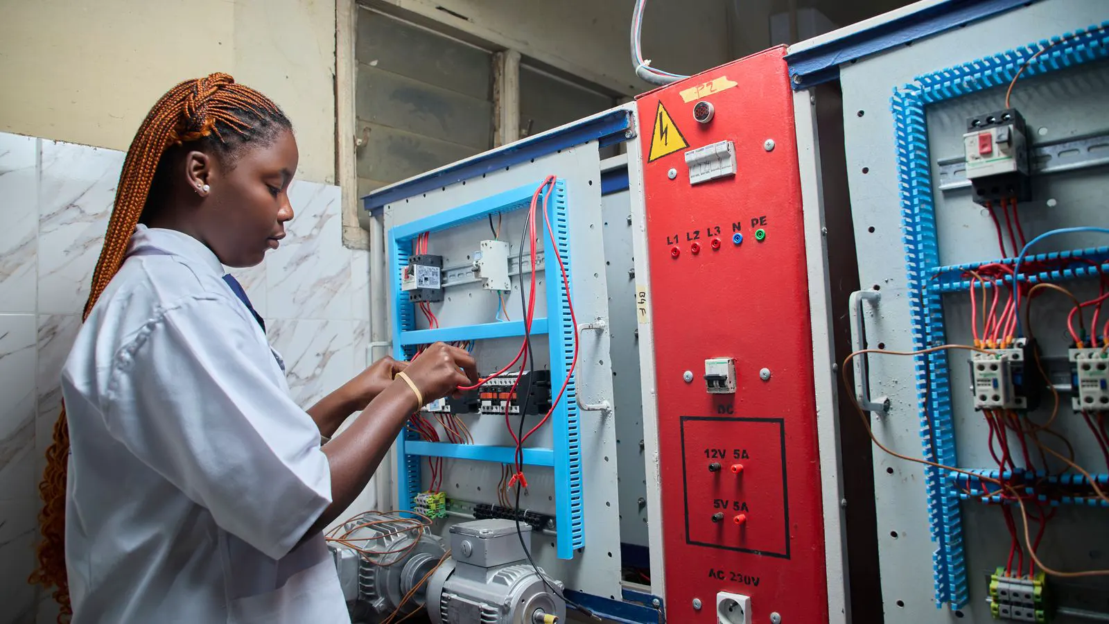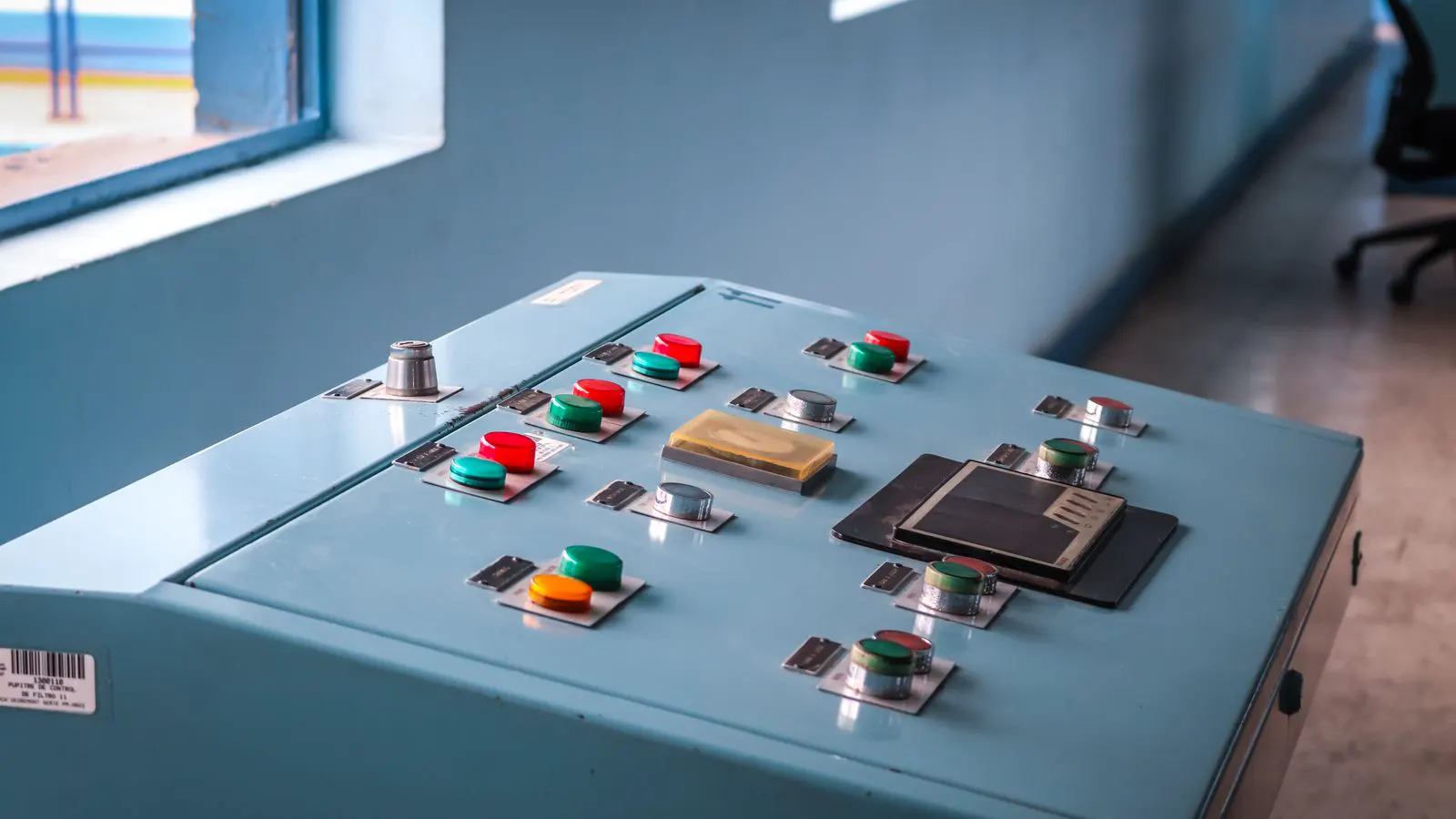
Variable speed drives adjust pump speed to match actual process demand, reducing electricity consumption by aligning motor output with fluid requirements. Proper sizing, control integration, and maintenance are required for safe and cost-effective implementation.
- Variable speed drives cut pump energy by reducing speed when demand is low, rather than throttling valves.
- A proper power study is required before installing drives to ensure motor and electrical infrastructure compatibility.
- Process control logic must be adjusted so the drive responds correctly to level, pressure, or flow setpoints.
- Regular inspection of drive components and pump alignment prevents reliability issues after speed changes.
- Verify savings with metered data after commissioning to confirm the expected energy reduction.
Pump electricity often accounts for a large share of plant utility bills. Fixed-speed operation wastes energy whenever the process does not require full flow. Variable speed drives change the motor speed to match the required volume, pressure, or level. This method reduces pump energy without changing the pump itself.
Why fixed-speed operation wastes energy
Pumps are designed for a specific operating point. When the process needs less fluid, the operator usually closes a control valve to restrict flow. The motor still runs at full speed. The valve converts the extra hydraulic energy into heat. This creates two problems. The electrical load stays high, and the valve wears quickly.
The affinity laws show that power is proportional to the cube of speed. Reducing speed by one third cuts power to roughly one eighth. This difference explains why variable speed drives provide significant savings. The pump still moves the fluid, but at a lower head. The motor draws less current. The result is lower electricity cost and reduced mechanical stress.
Prerequisites before installation
A successful installation requires a clear understanding of the existing system. Start with a review of the process requirements. Identify the minimum and maximum flow rates. Check the pressure setpoints. Confirm the operating level ranges.
Next, inspect the electrical supply. The motor nameplate lists the full load current. The variable speed drive must be sized to handle that current plus a margin for starting and harmonics. The supply voltage must be stable. If the plant uses a shared transformer, check the capacity.
The pump itself needs inspection. Worn bearings, damaged seals, or cavitation issues will not improve with a drive. The pump curve must support the reduced speed operation. Some pumps lose efficiency at low speeds. The operating point must remain stable across the speed range.
Step 1: Perform a load profile study
Record the pump operating conditions over a representative period. Use data loggers or manual readings. Note the flow, pressure, and valve position. Identify the percentage of time the pump runs at full speed and the percentage at partial load.
This data defines the savings potential. If the pump runs at full speed twenty percent of the day and at low demand eighty percent of the day, the savings are substantial. If the process requires constant flow, the benefit is minimal. The study also reveals control instability. If the level control is hunting, the drive will make the problem worse.
Step 2: Select the correct drive type
Choose a drive that matches the motor and application. A standard induction motor often pairs with a general-purpose drive. For high power or harsh environments, a direct-on-line alternative or a specialized drive may be needed. The drive rating must exceed the motor full load current.
Consider the control signals. The process control system needs to send a speed command. A 4 to 20 milliamp signal is common. A 0 to 10 volt signal also works. The drive must accept the signal type. If the existing system uses a different signal, a converter is required.
Check the cooling requirements. Drives generate heat. The enclosure must allow adequate ventilation. In dusty or wet locations, the enclosure rating must match the environment. A fan-cooled unit may need a filter. A sealed unit is better for aggressive atmospheres.
Step 3: Size the drive and motor
Match the drive output to the motor nameplate. The drive should not be significantly oversized. An oversized drive can cause control instability and inefficient operation. An undersized drive will trip under load.
Verify the motor insulation class. Standard motors are Class B or Class F. A variable speed drive changes the voltage waveform. This can stress the insulation. If the motor is older or has low insulation, a reactor or a Class H motor may be needed. Check the manufacturer data for the specific drive and motor combination.
The cable size must handle the harmonic current. Standard cable sizing may be insufficient. The drive output cable should be shorter than the input cable. Use shielded cables if the run length is long. Ground the shield at one end to reduce noise.
Step 4: Integrate with the process control system
Connect the drive to the control loop. The setpoint determines the speed. For a level control loop, the setpoint is the desired level. For a pressure loop, it is the target pressure. The control algorithm calculates the required speed.
Adjust the control parameters. A proportional controller may need a longer time constant. A proportional integral controller can handle steady state offset. A proportional integral derivative controller may be needed for fast response. The tuning affects stability. Poor tuning causes oscillation.
The drive must have a minimum speed limit. Some processes require a minimum flow to prevent recirculation or dry running. Set the lower limit accordingly. The upper limit should match the maximum safe speed. The drive should alarm if the speed falls below the limit for a set time.
Step 5: Configure protection and alarms
Program the drive to protect the motor and the pump. Overcurrent protection stops the drive if the current exceeds the motor rating. Overload protection trips the drive if the current stays high for a set time. Overvoltage and undervoltage protection handle supply issues.
Add alarms for low speed and high speed. A low speed alarm warns that the process is not meeting demand. A high speed alarm warns of a potential control failure. The alarm should trigger a visual indicator and a log entry. The alarm should not automatically stop the pump unless the process is unsafe.
Configure the fault response. A fault should stop the pump and isolate power if the cause is electrical. A process fault may allow the pump to coast down. The restart logic should prevent short cycling. A delay of several seconds is typical.
Step 6: Commission the drive
Before connecting the pump, test the drive with no load. Run the pump with the discharge valve closed if the pump type allows. Check the rotation. A wrong rotation direction will damage the pump. Adjust the phase order if needed.
Start with the pump at low speed. Gradually increase the speed. Monitor the current, voltage, and temperature. The current should rise as the speed increases. The temperature should remain within limits. The sound should be steady.
Connect the process control system. Verify the signal direction. A higher setpoint should produce a higher speed. Test the full range. Check the response time. The pump should stabilize without oscillation. Adjust the control parameters as needed.
Step 7: Monitor performance and maintain
After commissioning, record the energy consumption. Compare it with the pre-installation baseline. The savings should match the load profile prediction. If the savings are lower, check the control logic and the operating point.
Inspect the drive regularly. Clean the filters. Check the fan. Look for loose connections. The drive components degrade with heat and vibration. A loose terminal can overheat and fail.
Check the pump alignment and bearings. The speed changes affect the dynamic loads. The baseplate should remain level. The coupling should show no excessive wear. The seal should remain intact. Regular maintenance prevents failures that erase the energy savings.
Common mistakes to avoid
Sizing the drive too large is a frequent error. A drive with too much capacity cannot control the speed precisely. The pump may surge. The control loop may oscillate. The motor may overheat because the current limit is set too high.
Ignoring the pump curve is another mistake. Some pumps have a flat curve. They do not self-regulate. The control system must limit the flow. A pump with a steep curve is easier to control. The curve must be checked against the system curve.
Using the wrong cable type causes heating. The drive output is a non-sinusoidal waveform. The cable inductance changes. The voltage drop increases. The motor insulation stress rises. Use the cable type recommended by the drive manufacturer.
Not tuning the control loop leads to instability. The pump speed may oscillate around the setpoint. The valve may cycle. The energy savings disappear. The wear increases. The control parameters must be tuned for the specific system.
Verification step
Measure the energy before and after the installation. Use the same meter and the same operating conditions. Record the data for a full operating cycle. Compare the kilowatt hours. Calculate the savings percentage.
Check the operating point. The pump should run at a lower speed during low demand. The valve position should be higher than before. The temperature should be lower. The noise level should be reduced.
If the savings are lower than expected, review the control logic. The setpoint may be too high. The minimum speed may be too high. The pump may be running at a different operating point. Adjust the parameters and re-test.
A verification step confirms the investment. It provides a baseline for future improvements. It identifies any issues before they become major problems. The data supports the business case for additional installations.
When variable speed drives are not suitable
A pump may not benefit from a drive. If the process requires constant flow, the speed remains constant. The energy savings are minimal. If the pump is already at low speed due to system resistance, the benefit is small.
Some pumps are not suitable. Positive displacement pumps cannot reduce speed safely. They may cavitate or overheat. Some centrifugal pumps have poor efficiency at low speeds. The specific speed must be checked.
The electrical system may limit the option. If the supply is unstable, the drive may fault. If the transformer is overloaded, the harmonics may cause issues. A power quality study may be needed.
A cost-benefit analysis is required. The drive cost is higher than a fixed motor. The savings must offset the cost. The payback period must be acceptable. The installation may require control upgrades.
The decision depends on the specific application. The data must support the choice. A site assessment is necessary. The goal is to reduce pump energy safely and reliably.
Frequently asked questions
How much energy do variable speed drives save?
Savings depend on the load profile. Pumps that run at partial load for long periods save the most. A typical centrifugal pump can reduce power significantly when speed is lowered.
Can I add a variable speed drive to an existing motor?
Yes, if the motor and supply are compatible. Check the insulation class and the supply voltage. The drive must be sized to the motor. Cable changes may be required.
What is the main risk of using a variable speed drive?
Poor control tuning can cause instability. The pump may oscillate. The valve may cycle. The energy savings disappear. The wear increases.
Do I need to change the pump?
No, the pump usually stays the same. The drive changes the speed. The pump curve must support the new operating range. Check the minimum speed and the efficiency.
How do I verify the savings?
Meter the electricity before and after. Use the same operating conditions. Compare the kilowatt hours. Check the operating point and the valve position.